Basic physical processes of TL & OSL
In the most general sense, TL and OSL techniques measure the amount of
energy stored within the electronic lattice of insulators.
|
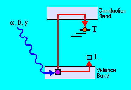
Trapping:
When thermoluminescent materials are exposed to ionising radiation
some of the electrons which are freed by the ionisation are given sufficient
energy to move through the crystal: they are said to enter the conduction
band. Structural defects in the lattice (vacancies, interstitial atoms,
and substitutional impurities) create localized charge deficits, which
act as traps T for the conduction electrons. Most electrons recombine or
are briefly trapped in very shallow traps, but a few are trapped at deep
traps and remain there over geological timescales (1-1000 Ma) if the material
is kept at room temperature. The now charge-deficient ion which contributed
the trapped charge becomes a luminescence centre L. |
|
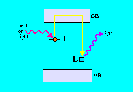
Recombination:
Electrons trapped in deep traps T do not readily recombine unless induced
to do so by natural "clock-resetting events", or under strictly controlled
laboratory conditions. Heat or light can eject charges (trapped electrons)
from traps T back into the conduction band and then they recombine with
luminescence centers L and give up their surplus energy by emitting visible
light. This phenomenon forms the basis of thermoluminescence and optical
stimulated luminescence.
|
A Second Explanation of TL Phenomena
 |
In order to understand the value of the information
contained in the TL observation, it is helpful to understand something
about the process that produces the light emission. The crystal is rendered
capable of emitting TL by exposure to ionising radiation, which redistributes
electrical charges within the material. Some of charged particles become
confined at trap sites, while others are localised at luminescence
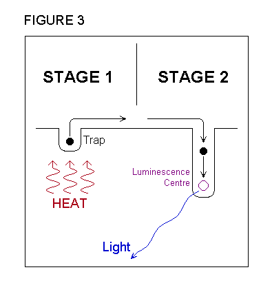
centres . During the TL measurement, light is produced in a two stage
process, which is illustrated in figure 3. In the first stage, the charges
held at trap sites are released by the action of heat and become mobile.
In the second stage, these charges are attracted to oppositely charged
particles at the luminescence centres, combine with them, and release energy
in the form of light. At the end of the measurement, the crystal contains
fewer centres with unpaired charges, and thus returns to a situation similar
to the one it was in prior to radiation exposure. |
Study of thermoluminescence in the laboratory involves measurement of the
emitted light intensity as a function of the temperature of the sample,
typically up to 500 C. The TLD is raised to about 200 C for readout. Further
heating to about 400 C, depending on the material, anneals the TLD so enabling
them to be re-used. Because of the very low light intensity involved, a
photomultiplier is used to detect individual emitted photons which are
proportional to the radiation dose absorbed by the material.. The photomultiplier
is preceded by optical filters to select the wavelength range of interest
from the particular sample material. A microcomputer controls the heating
and collects the data. Since natural crystals from different places may
contain different trace impurities and it is these trace impurities which
determine the thermoluminescence characteristics of the crystals, all samples
must be investigated individually. Relevant characteristics which may need
to be measured include, the form of relationship between thermoluminescence
intensity and radiation dose, the sensitivity to irradiation by alpha particles
and to beta particle irradiation, the thermal stability of electron traps
(by controlled heating prior to measurement), the bleaching of the thermoluminescence
signal by sunlight.
In practice, the systematic observation of TL involves the continuous
measurement of the varying intensity of light output as the material is
progressively heated. During the measurement, the heat input is controlled
to produce a constant rate of temperature increase, so that the temperature
rise is proportional to the time that has elapsed since the start of the
heating. As a result, the graph of TL intensity plotted against time also
represents the output of TL as a function of temperature and this graph
is referred to as a glow curve and it is a unique product of the
TL measurement. .
Glow curve information may be used to detect and separate different
TL processes which contribute to the total light intensity, and allows
the properties of the component signals to be determined. This knowledge,
in turn, informs the sampling strategy for optimising the TL signal most
suited for dating purposes. Additionally, the glow curve provides the means,
firstly, to distinguish between thermally stable and unstable luminescences,
and secondly, to detect the likely condition of sedimentary TL immediately
after deposition.
The glow curve owes its significance to the fact that the temperature
of the crystal defines the amount of thermal energy which is available
for initiating the first stage of the TL process. It requires more thermal
energy to release charge from a deep trap than from a shallow trap, so
that the TL associated with a deeper type of trap appears at a higher temperature.
Thus, the temperature scan which constitutes the TL glow curve represents
a scan through the various types of trap present in the crystal.
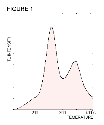
| Figure 1 shows the variation of
TL intensity against temperature observed during the heating of a sample
of calcite. As seen in this example, the glow curve is formed from a number
of peaks having different heights, widths and shapes. The TL belonging
to each peak is generated by a particular structural element within the
crystal, by a mechanism which is described below. The term TL signal
is used to refer to the luminescence produced by a given structure. The
positions and shapes of the TL peaks are related to the characteristics
of these structures, which are in turn typical of the crystal containing
them. |
 |
 |
In addition to a characteristic glow
curve, the light emitted during TL
also possesses a particular colour. This colour can
be expressed in terms of the way that the light's intensity varies
with its wavelength. The graph of light intensity against
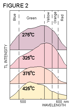
wavelength is called the emission spectrum . During the TL
measurement, in addition to the variations of light intensity,
there are also alterations in the colour of the light. This is
illustrated in figure 2, which shows how the emission spectrum
of calcite changes its shape as the temperature increases.
By contrast, the colour of the light emitted is determined, in the second
stage of the TL process, by the type of luminescence centre where the charges
combine. Since the form of the glow curve is related to the charge traps,
and the emission spectrum is determined by the luminescence centres, the
TL measurement provides information about both stages of the luminescence
process simultaneously. |
  |
