03.11.1998
EP 425
FIRST MIDTERM
1. i -) (4
Pts.) Perform the necessary operations;
a-) (1-j2)+(-1-j2) b-) (1+j5)x(4+j2) c-) ![]() d-)
d-) ![]()
ii -)
(7 Pts.) Convert the following complex numbers from rectangular to polar or
polar to rectangular;
a-) 1+j2 b-)
–1+j2 c-)
–5-j5 d-)
![]() e-)
e-) ![]() f-)
f-) ![]() g-)
g-) ![]()
iii-)
(3 Pts.) Express the following waves as phasor;
a-) ![]() b-)
b-) ![]() c-)
c-) ![]()
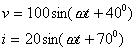
iv-) (4 Pts.) The current through a 0.1 H coil is given. Find the
sinusoidal expression for the voltage across the coil. Sketch the v and i curves.
![]()
v-) (4 Pts.) The voltage across a 1 mF
capacitor is given. What is the sinusoidal expression for the current. Sketch
the v and i curves.
![]()
vi-) (3 Pts.) Determine average power delivered to network having the
following input voltage and current.
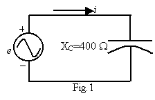
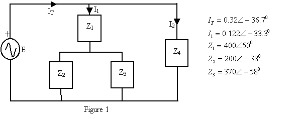
2. (25
Pts.) Calculate Z4 of figure 1;
3. (20
Pts.) For the circuit of figure 1; obtain mesh circuit equations. Do not solve.
(w=12.5 krad/sec)
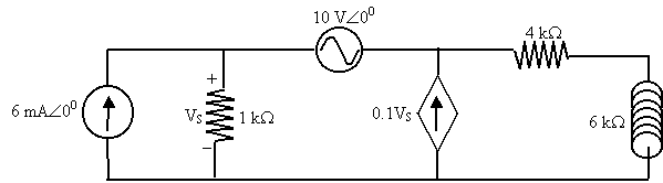
4. (30
Pts.) Write the nodal equations for the circuit and solve for E1


04.01.1999
EP 425
FINAL EXAMINATION
Time Duration : 120 Mins.
1.
a-) For a practical tank
circuit, derive the formulas of 3 dB (cut-off) frequencies w1 and w2.
b-) For the circuit shown in figure 1 find the
resonance frequency w0 at which E and I are in phase. What is the value of
ZT at this frequency ? Derive an expression for the quality factor Q
of this circuit.
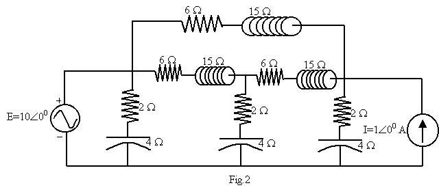
2.
Find the waveform of the
voltage v(t) across the current
source in the circuit shown in figure 2 given that e(t)=2.828sin(5000t) V and is(t)=1.414cos(10000t)
A.
3.
Find the input impedance Zin
of the network shown in figure 3.
Good Luck
Dr.A.N.Yazıcı
22.11.1999
EP 425 (Elect.Circuit Analyses)
Time Duration :
100 Mins.
- a-) Find the peak and effective values of the
following sinusoidal waveforms
i- ) v=7.07sin377t Volt ii -) i=16x10-3sin(377t-100)
Amper
b-)
Find the phase relationship between the waveforms of each set
i -) v=2sin(wt-600) ii -) v=35sin(wt-200)
i=3sin(wt+300) i=7cos(wt-1100)
c-) For the given pairs of
voltages and currents in question 1b, indicate whether the element involved is
a capacitor inductor, resistor, or combinations of them.
 d-) In given 1, I=3sin(377t-200)
i-) Find the sinusoidal expression for e
ii-) Find the value of the capacitance C
in microfarads
iii-) Find the average power loss in the
capacitor.
2.
 Write the mesh equations for
the network of figure 2 and determine the current through the inductive
elements.
Write the mesh equations for
the network of figure 2 and determine the current through the inductive
elements.
Fig.2
 Write
the nodal equations for the network of figure 3.
Write
the nodal equations for the network of figure 3.
.....12.1999
EP 425
Electrical Circuit Analyses
Second Midterm
Time Duration : 110 mins.
- a-)
Find the bandwidth (BW) of a series resonant circuit having a resonant
frequency of 6 kHz and a Qr of 15.
b-) Find the cutoff frequencies.
c-) If the resistance of the circuit ar
resonance is 3 W, what are
the values of reactances.
d-) What is the power dissipated at the
half-power frequencies if the maximum current flowing through the circuit is
0.5 A?
- For
the parallel resonant network of given figure:
 a-) Calculate the resonance frequency.
b-) Find the total impedance at resonance.
c-) determine the quality factor Qr.
d-) Determine the 3-dB frequencies.
e-) Determine the bandwidth (BW).
f-) Calculate Vmax and Vrms
voltages.
g-) Decide whether this circuit can be
used as a good resonant circit or not.
- a-) Draw and explain the graphs
(V versus f) of filters which is used in electronic industries.
b-)
Design a high-pass RC filter to have a corner frequency of 2 kHz, given a
capacitor of 0.1 mF. Sketch the
normalized gain Av for a frequency range of 0.1fc to 10 fc.
Good Luck
Dr.A.N.Yazıcı
21.01.2000
EP 425
Electrical Circuit Analyses
Final
Exam (Time Duration : 120 mins.)
Three
Questions=100 Pts. Four Questions=130 Pts.
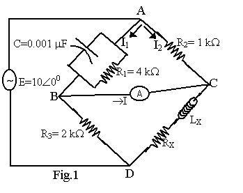
1. The
Wheastone bridge can be used
to measure an unknown impedance
by balancing the bridge. The balance
condition is satisfied when I=0 A
and at this condition VAB=VAC
and VCD=VBD. Determine the
unknown component values
(RX and LX) required to balance
the bridges in Fig.1.
2. For the
circuit in Fig.2, find the resonance
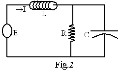 frequency
wr at
which E and I are in
frequency
wr at
which E and I are in
phase. What is the value of ZT at this
frequency and simplify it also its
simplest form. Derive an expression for
the quality factor Q and BW of this circuit.
3. a.
Design a radio receiver circuit (i.e a filter) that permits to pass the frequency
from 88 MHz to 108 MHz.
b.
Design a radio transmitter circuit (i.e a.tank circuit) that has a resonance
frequency at 98 MHz. (Assume that all of the used resistors are 1 kW)
4. 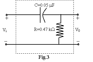 a.
Sketch the idealized Bode plot for
a.
Sketch the idealized Bode plot for
AV=V0/Vi for the high pass filter
of Fig.3.
b.
Using the results of part (a),
sketch the actual frequency
response for the same frequency
range.
c.
Determine the decibel level at
fc, fc/2,
and 2fc,.
d.
Determine the gain AV=V0/Vi
as f=fc,
fc/2, and 2fc.
Good
Luck
Dr.A.N.Yazıcı
26.7.2001
EP 425
Electrical Circuit Analyses
First
Midterm (Time Duration : 100 mins.)
(Summer
School)
1-)
a-) Express the following waves as phasor;
i-) ![]() ii-)
ii-)
![]() iii-)
iii-) ![]()
b-) The current through a 0.1 H coil is given. Find the sinusoidal
expression for the voltage across the coil. Sketch the v and i curves.
![]()
2-)
Calculate Z4 of figure 1;
3-)
Write the mesh equations for the network of figure 2.
Good Luck
Dr.A.N.Yazıcı